Introduction:
This guide serves as a foundational resource for beginners looking to understand SystemVerilog testbench structure. It focuses on a simple Design Under Test (DUT) to provide clear insights into the various components of a testbench. By the end of this guide, users will have a solid understanding of different testbench components and will be capable of writing and comprehending complex testbenches.
Table of Contents
DUT
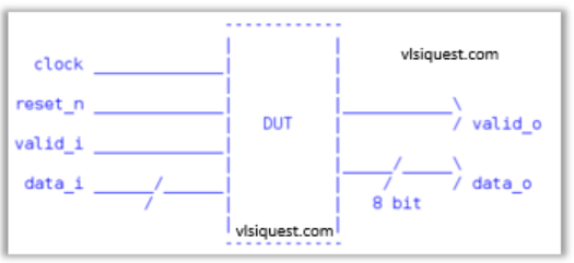
This DUT(RTL) is simple 8 bit shift register. This module takes four inputs: clock, reset_n, valid_i, and data_i, and provides two outputs: valid_o and data_o. When reset_n is low, indicating a reset condition, it sets the output valid flag to 0 and the output data to 0. Otherwise, it passes the input data and valid flag directly to the output.


Verification Plan
To verify that the RTL output (data_o) matches the input data (data_i) when the valid flag (valid_i) is asserted. With this we can ensure that the DUT correctly processes the input data and generates the expected output data when the valid flag is asserted.
Stimulus Generation:
- Generate random input data (data_i) along with the valid flag (valid_i).
- Ensure that the valid flag is asserted when valid data is provided.
Testbench Setup
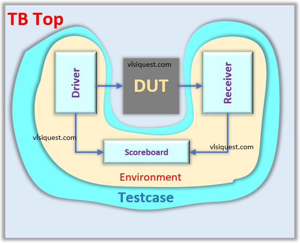
The SystemVerilog testbench structure typically consists of several key components and follows a hierarchical organization. Here is an overview of the key elements and their structure:
- Top Level: Testbench module interacting with the design under test (DUT).
- Test Cases: Define specific verification scenarios. This is program block.
- Environment: Contains Drivers, Monitors and Scoreboards.
- Interface: An interface is a bundle of signals or nets through which a testbench communicates with a design.
- Driver: The driver is responsible for driving data into the input interfaces of the DUT. It converts transaction-level data into physical signals that are applied to the DUT’s. inputs.
- Monitors: The monitor captures and monitors the signals and transactions on the output interfaces of the DUT.
- Scoreboard: Compares expected vs. actual results.
Testbench Structure

- Driver and Monitor are connected to DUT through ‘interface’.
- The scoreboard receives data input to the DUT (expected data or reference data) and data output from the DUT (received data) through mailbox from the Driver and Monitor respectively.
- The ‘interface’ and ‘mailbox handles’ are connected to their respective blocks by passing the handles as arguments in the new() function.
DUT Code
module dut(
    input        clock,    // Clock input
    input        reset_n,  // Active-low reset input
    input        valid_i,  // Input valid flag
    input  [7:0] data_i,   // 8-bit input data
    output       valid_o,  // Output valid flag
    output [7:0] data_o    // 8-bit output data
  );

  reg       valid_o;
  reg [7:0] data_o;

  always @ (posedge clock or negedge reset_n)
  begin
    if(!reset_n)
    begin
     valid_o <= 1'b0;
     data_o  <= 8'h0;
    end
    else
    begin
     data_o  <= data_i;
     valid_o <= valid_i;
    end
  end
endmodule
					//-------------------------------------------
// interface
//-------------------------------------------
interface dut_interface(input bit clock, reset_n);
    logic       valid_i;
    logic [7:0] data_i;
    logic       valid_o;
    logic [7:0] data_o;

    clocking cb@(posedge clock);
     default input #1 output #1;
     output  valid_i;
     output  data_i;
     input  valid_o;
     input  data_o;
   endclocking

endinterface
Driver
					//-------------------------------------------
// driver
//-------------------------------------------
class driver;
   bit     [7:0] data;
   mailbox #(bit [7:0])  mbx;
   virtual dut_interface vif;

   function new(virtual dut_interface vif, mailbox #(bit [7:0]) mbx);
     this.vif = vif;
     this.mbx = mbx;
     $display("%5t: driver: new()", $realtime);
   endfunction

   task start();
     $display("%5t: driver: start()", $realtime);
     for(int itr=0; itr<10; itr++)
     begin
      std::randomize(data);
      mbx.put(data);
      vif.cb.valid_i <= 1'b1;
      vif.cb.data_i  <= data;
      @(vif.cb);
     end
   endtask:start
endclass:driver
Monitor
					//-------------------------------------------
// monitor
//-------------------------------------------
class monitor;
   bit     [7:0] data;
   mailbox #(bit [7:0])  mbx;
   virtual dut_interface vif;

   function new(virtual dut_interface vif, mailbox #(bit [7:0]) mbx);
     this.vif = vif;
     this.mbx = mbx;
     $display("%5t: monitor: new()", $realtime);
   endfunction

   task start();
     $display("%5t: monitor: start()", $realtime);
     forever
     begin
      @(vif.cb);
      if(vif.cb.valid_o==1'b1)
      begin
       data = vif.cb.data_o;
       mbx.put(data);
      end
     end
   endtask:start
endclass:monitor
Scoreboard
					//-------------------------------------------
// scoreboard
//-------------------------------------------
class scoreboard;
   int                   err_cnt;
   bit     [7:0]         rcv_data;
   bit     [7:0]         drv_data;
   mailbox #(bit [7:0])  mon2sb;
   mailbox #(bit [7:0])  drv2sb;

   function new(mailbox #(bit [7:0]) mon2sb, drv2sb);
     this.mon2sb = mon2sb;
     this.drv2sb = drv2sb;
     $display("%5t: scorebooard: new()", $realtime);
   endfunction

   task start();
     $display("%5t: scorebooard: start()", $realtime);
     forever
     begin
      mon2sb.get(rcv_data);
      $display("%5t: scorebooard: Scoreboard received data from monitor (0x%x)", $realtime, rcv_data);
      drv2sb.get(drv_data);
      if(rcv_data == drv_data) begin
       $display("%5t: scoreboardd: Data Matched (0x%x)", $realtime, rcv_data);
      end
      else begin
       err_cnt++;
       $display("%5t: scoreboardd: Error: Data MisMatched expected=0x%x, receved=0x%x", $realtime, drv_data, rcv_data);
      end
     end
   endtask:start

endclass:scoreboard
Environment
					//-------------------------------------------
// environment
//-------------------------------------------
class environment;
   driver                drv;
   monitor               mon;
   scoreboard            sb;
   mailbox #(bit [7:0])  mon2sb;
   mailbox #(bit [7:0])  drv2sb;
   virtual dut_interface vif;

   function new(virtual dut_interface vif);
     this.vif = vif;

     mon2sb = new();
     drv2sb = new();
     sb  = new(mon2sb, drv2sb);
     drv = new(vif,    drv2sb);
     mon = new(vif,    mon2sb);
     $display("%5t: environment: new()", $realtime);
   endfunction

   task start();
     $display("%5t: environment: start()", $realtime);
     fork
       sb.start();
       drv.start();
       mon.start();
     join_any
     $display("%5t: environment: start() - completed", $realtime);
   endtask:start


endclass:environment
Testcase
					//-------------------------------------------
// testcase
//-------------------------------------------
program testcase(dut_interface vif);
  environment env;

  initial begin
   $display("%5t: testcase: initial", $realtime);

   env = new(vif);

   wait(vif.reset_n == 1'b1);
   repeat(5) @ (posedge vif.clock);

   env.start();

   repeat(10) @ (posedge vif.clock);
   $finish;
  end
endprogram
TB Top
					//-------------------------------------------
// tb_top
//-------------------------------------------
module tb_top();

  bit  clock;
  bit  reset_n;

  dut_interface intf(clock, reset_n);

  testcase tc(intf);

  dut dut_i(
    .clock    (intf.clock),
    .reset_n  (intf.reset_n),
    .valid_i  (intf.valid_i),
    .data_i   (intf.data_i),
    .valid_o  (intf.valid_o),
    .data_o   (intf.data_o)
   );

  always #5 clock = !clock;

  initial
  begin

    intf.valid_i <= 0;
    intf.data_i  <= 0;

    reset_n <= 1'b0;
    repeat(5) @ (posedge clock);
    reset_n <= 1'b1;
  end

endmodule
Assignment
- Change the stimulus and randomly toggle valid_i signal.
- Enhance the DUT, introduce a pipeline delay so that data requires multiple clock cycles to exit the DUT. Additionally, implement a queue within the scoreboard to store expected data before performing comparisons.

