[wpbread]
In digital design and verification, precise signal timing is paramount to prevent race conditions and ensure the system operates reliably. Signals must be driven or sampled concerning specific clock edges to maintain synchronization between the Design Under Test (DUT) and the testbench.
Table of Contents
SystemVerilog Clocking Block
SystemVerilog clocking blocks are invaluable for managing this timing synchronization. They establish a framework for organizing and specifying signal timing in relation to a designated clock. Here are key points about clocking blocks:
- Clocking blocks bring together signals synchronous to a specific clock, making their timing explicit.
- They define when signals are sampled and driven by the testbench, offering a synchronization reference for both the DUT and testbench.
- A clocking block is defined using the
clockingandendclockingkeywords.
- Depending on the environment, a testbench can contain one or more clocking blocks, each containing its own clock and assembles signals that are synchronous to this clock.
- The same signals— clock, inputs, inouts, or outputs—can appear in more than one clocking block.
- Multiple clocking blocks cannot be nested.
- A clocking block can only be declared inside a module, interface, checker, or program.
- They cannot be declared inside functions, tasks, or packages or outside all declarations in a compilation unit.
clocking skew
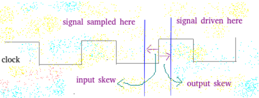
Clocking block defines clocking_skew that determines how many time units away from the clock event a signal is to be sampled or driven.
- input skew – the signal is sampled at skew time units before the clock event.
- output_skew – signals are driven skew simulation time units after the clock event.
Unless otherwise specified,
 the default input skew is 1step and
 the default output skew is 0.
- A skew shall be a constant expression and can be specified as a parameter.
- If the skew does not specify a time unit, the current time unit is used.
- Each signal can have explicit skew specified.
					clocking cb @(posedge clk);
    input #1step addr, data;
    input #2ns   enable;
    output #2ns  ack;
endclocking
- A single skew can be specified for the entire block by using a default clocking skew.
					clocking cb @(posedge clk);
    default input #1ns output #1ns;
    input      addr, data;
    input #2ns enable;
    output     ack;
endclocking
- The skew can be specified as the specific edge of the signal.
default input #1step output negedge; // outputs driven on the negedge clk
Actual signal Vs Clocking Block signal
A clocking block maintains a synchronized copy of signals relative to a specified clock, taking into account input and output skew. This code illustrates the distinction between an actual signal and a clocking block signal. Check ‘sig’ and ‘sig1’ ion the waveform snapshot.
					module top;
  bit sig;
  bit sig1;
  bit clk;
  bit clk;

  clocking cb @(posedge clk);
    input sig;
  endclocking

  assign sig1 = cb.sig;

  always #5 clk = ~clk;

  initial begin
    $dumpfile("dump.vcd"); $dumpvars;
    #15 sig <= 1;
    #11 sig <= 0;
    #20 sig <= 1;
    #10 sig <= 0;
    #8  sig <= 1;
    #300 $finish;
  end

endmodule
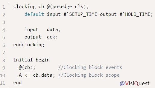
Clocking block scope
The clocking signals are accessed via the clocking block name and the dot (.) operator.
cb.data //signal data in clocking block cb
#1step
A 1step input skew allows input signals to sample their steady-state values in the time step immediately before the clock event (i.e., in the preceding Postponed region).(The step time unit is equal to the global time precision. Defined by `timescale)
#0 skew
Inputs with explicit #0 skew shall be sampled at the same time as their corresponding clocking event, but to avoid races, they are sampled in the Observed region.
Likewise, clocking block outputs with no skew (or explicit #0 skew) shall be driven at the same time as their specified clocking event, in the Re-NBA region.
Hierarchical expressions
Any signal in a clocking block can be associated with an arbitrary hierarchical expression.
					clocking cb @(posedge clk);
   input   #1step state  = top.cpu.state;
endclocking
Slices and concatenations
They can be used to declare slices and concatenations
					clocking cb @(posedge clk);
 input #1step instruction = {opcode, regA, regB[3:1]};
endclocking
Clocking block events
Upon processing its specified clocking event, a clocking block shall update its sampled values before triggering the event associated with the clocking block name. This event shall be triggered in the Observed region.
					clocking cb @(posedge clk);
    input  addr;
 endclocking

//(A) - triggers on clocking block event
always @ (cb) $display(cb.addr);

//(B) - triggers on clock
always @ (posedge clk) $display(cb.addr);
(A) always @ (cb) $display(cb.addr);
Clocking block events triggers in observed region, so first always block guarantees to display the updated sampled value of signal data.
(B)always @ (posedge clk) $display(cb.addr);
Second always block may encounter race conditions and may display old or updated value.


